Boiler feed water
A boiler is a device for generating steam,
which consists of two principal parts: the furnace, which provides heat,
usually by burning a fuel, and the boiler proper, a device in which the heat
changes water into steam. The steam or hot fluid is then recirculated out of
the boiler for use in various processes in heating applications.
The water circuit of a water boiler can be
summarized by the following pictures:
|
The boiler receives the feed water, which
consists of varying proportion of recovered condensed water (return water)
and fresh water, which has been purified in varying degrees (make up water).
The make-up water is usually natural water either in its raw state, or
treated by some process before use. Feed-water composition
therefore depends on the quality of the make-up water and the amount of
condensate returned to the boiler. The steam, which escapes from the boiler,
frequently contains liquid droplets and gases. The water remaining in liquid
form at the bottom of the boiler picks up all the foreign matter from the
water that was converted to steam. The impurities must be blown down
by the discharge of some of the water from the boiler to the drains. The
permissible percentage of blown down at a plant is strictly limited by
running costs and initial outlay. The tendency is to reduce this percentage
to a very small figure.
|
|
Proper treatment of boiler feed water is an
important part of operating and maintaining a boiler system. As steam is
produced, dissolved solids become concentrated and form deposits inside the
boiler. This leads to poor heat transfer and reduces the efficiency of the
boiler. Dissolved gasses such as oxygen andcarbon dioxide
will react with the metals in the boiler system and lead to boiler corrosion.
In order to protect the boiler from these contaminants, they should be
controlled or removed, trough external or internal treatment. For more
information check the boiler water treatment web
page.
In the following table you can find a list
of the common boiler feed water contaminants, their effect and their possible
treatment.
IMPURITY
|
RESULTING
IN
|
GOT
RID OF BY
|
COMMENTS
|
Soluble
Gasses
|
|
|
|
Hydrogen
Sulphide (H2S)
|
Water smells like rotten eggs: Tastes
bad, and is corrosive to most metals.
|
Aeration, Filtration, and Chlorination.
|
Found mainly in groundwater, and polluted
streams.
|
|
|
Corrosive, forms carbonic acid in
condensate.
|
Deaeration, neutralization with alkalis.
|
Filming, neutralizing amines used to
prevent condensate line corrosion.
|
|
|
Corrosion and pitting of boiler tubes.
|
Deaeration & chemical treatment
with (Sodium Sulphite or Hydrazine)
|
Pitting of boiler tubes, and turbine
blades, failure of steam lines, and fittings etc.
|
|
|
|
|
|
|
|
Sludge and scale carryover.
|
Clarification and filtration.
|
Tolerance of approx. 5ppm max. for most
applications, 10ppm for potable water.
|
Organic
Matter
|
Carryover, foaming, deposits can clog
piping, and cause corrosion.
|
Clarification; filtration, and chemical
treatment
|
Found mostly in surface waters, caused by
rotting vegetation, and farm run offs. Organics break down to form organic
acids. Results in low of boiler feed-water pH, which then attacks boiler
tubes. Includes diatoms, molds, bacterial slimes, iron/manganese bacteria.
Suspended particles collect on the surface of the water in the boiler and
render difficult the liberation of steam bubbles rising to that surface..
Foaming can also be attributed to waters containing carbonates in solution
in which a light flocculent precipitate will be formed on the surface of
the water. It is usually traced to an excess of sodium carbonate used in
treatment for some other difficulty where animal or vegetable oil finds its
way into the boiler.
|
Dissolved
Colloidal Solids
|
|
|
|
Oil
& Grease
|
Foaming,
deposits in boiler
|
Coagulation & filtration
|
Enters boiler with condensate
|
|
|
Scale deposits in boiler, inhibits heat
transfer, and thermal efficiency. In severe cases can lead to boiler tube
burn thru, and failure.
|
Softening, plus internal treatment in
boiler.
|
Forms are bicarbonates, sulphates,
chlorides, and nitrates, in that order. Some calcium salts are reversibly
soluble. Magnesium reacts with carbonates to form compounds of low
solubility.
|
Sodium,
alkalinity, NaOH, NaHCO3, Na2CO3
|
Foaming, carbonates form carbonic acid in
steam, causes condensate return line, and steam trap corrosion, can cause
embrittlement.
|
Deaeration of make-up water and
condensate return. Ion exchange; deionization, acid treatment of make-up
water.
|
Sodium salts are found in most waters.
They are very soluble, and cannot be removed by chemical precipitation.
|
Sulphates
(SO4)
|
Hard scale if calcium is present
|
Deionization
|
Tolerance limits are about 100-300ppm as
CaCO3
|
|
|
Priming, i.e. uneven delivery of steam
from the boiler (belching), carryover of water in steam lowering steam
efficiency, can deposit as salts on superheaters and turbine blades.
Foaming if present in large amounts.
|
Deionization
|
Priming, or the passage of steam from a
boiler in "belches", is caused by the concentration sodium
carbonate, sodium sulphate, or sodium chloride in solution. Sodium sulphate
is found in many waters in the USA, and in waters where calcium or
magnesium is precipitated with soda ash.
|
|
|
Deposits in boiler, in large amounts can
inhibit heat transfer.
|
Aeration, filtration, ion exchange.
|
Most common form is ferrous bicarbonate.
|
|
|
Hard scale in boilers and cooling
systems: turbine blade deposits.
|
Deionization; lime soda process,
hot-lime-zeolite treatment.
|
Silica combines with many elements to
produce silicates. Silicates form very tenacious deposits in boiler tubing.
Very difficult to remove, often only by flourodic acids. Most critical
consideration is volatile carryover to turbine components.
|
The principal difficulties caused by water
in boiler are:
|
Steam Plants
Water
in the form of steam has the ability to store great amounts of energy. With
it's ease of control and delivery, steam brought the advent of power to the
shipping world.
There
are still some steam powered vessels such as ULCC ( Ultra Large Crude Carrier )
where steam turbines can provide the necessary, high power shaft requirements
to propel the ship. However it's time as passed, most ships nowadays use the
more economical diesel burning heavy fuels.
Although
boilers may no longer be commonplace for ship propulsion they are almost
guaranteed to be one boiler for various duties on board a ship. Duties like
heating cargo, fuel, and accommodations. Some ships also use boilers for
auxiliary power. Such as deck winches and pumps, where electrical machines
would prove to be a hazard as in the oil industry.
 Steam
Theory
Steam
Theory
Within the boiler, fuel and air are force
into the furnace by the burner. There, it burns to produce heat. From there,
the heat (flue gases) travel throughout the boiler. The water absorbs the heat,
and eventually absorb enough to change into a gaseous state - steam.
To the left is the basic theoretical design
of a modern boiler. Boiler makers have developed various designs to squeeze the
most energy out of fuel and to maximized its transfer to the water. But it all
boils down, pardon the pun, to the basic design shown here.
Below are a description of the most accepted
variations of the basic principles ( above left ).
The
water tube boiler
As you can see, the Babcock Marine Water Tube
Boiler (below) looks very complicated. Thousands of tubes are placed in
strategic location to optimize the exchange of energy from the heat to the
water in the tubes. These types of boilers are most common because of their
ability to deliver large quantities of steam.
The large tube like structure at the top of
the boiler is called the steam drum. You could call it the heart of the boiler.
That's where the steam collects before being discharged from the boiler. The
hundreds of tube start and eventually end up at the steam drum.
Water enters the boiler, preheated, at the
top. The hot water naturally circulates through the tubes down to the lower
area where it is hot. The water heats up and flows back to the steam drum where
the steam collects. Not all the water gets turn to steam, so the process starts
again. Water keeps on circulating until it becomes steam.
Meanwhile, the control system is taking the
temperature of the steam drum, along with numerous other readings, to determine
if it should keep the burner burning, or shut it down.
As well, sensors control the amount of water
entering the boiler, this water is know as feed water. Feed water is not your
regular drinking water. It is treated with chemicals to neutralize various
minerals in the water, which untreated, would cling to the tubes clogging or
worst, rusting them. This would make the boiler expensive to operate because it
would not be very efficient.
On the fire side of the boiler, carbon
deposit resulting from improper combustion or impurities in the fuel can
accumulate on the outer surface of the water tube. This creates an insulation
which quickly decrease the energy transfer from the heat to the water. To
remedy this problem the engineer will carry out soot blowing. At a specified
time the engineer uses a long tool and insert it into the fire side of the
boiler. This device, which looks like a lance, has a tip at the end which
"blows" steam. This blowing action of the steam "scrubs"
the outside of the water tubes, cleaning the carbon build up.
Water tube boilers can have pressures from 7
bar (one bar = ~15 psi) to as high as 250 bar. The steam temperature's can vary
between saturated steam, 100 degrees Celsius steam with particle of water, or
be as high as 600 - 650 degrees Celsius, know as superheated steam or dry steam
(all water particle have been turn to a gaseous state).
The performance of boiler is generally
referred to as tons of steam produced in one hour. In water tube boilers that
could be as low as 1.5 t/hr to as high as 2500 t/hr. The larger boilers would
be land based, your local power company would mo st likely operate one. In British Columbia, large boilers
are most common at Pulp and Paper plants.
st likely operate one. In British Columbia, large boilers
are most common at Pulp and Paper plants.
Foster Wheeler (USA/UK), Babcock (USA/UK/Ger), Combustion Engineering
(USA), and Kawasaki Heavy Industries
(Japan) are some of the more prominent manufacturer of boilers. Click on the
picture to the right to view a full size diagram of a Foster Wheeler ESD III
water tube boiler.
The
fire tube boiler
This type of boilers started it all. This is
the original design of boiler which brought the tide of power to the marine
world. If you are ever in  Vancouver,
BC, the SS Master, a turn of the century tugboat, is open for the public to
view at the Vancouver Maritime Museum.
It is operational, and a fine example of ship using a fire tube boiler.
Vancouver,
BC, the SS Master, a turn of the century tugboat, is open for the public to
view at the Vancouver Maritime Museum.
It is operational, and a fine example of ship using a fire tube boiler.
On a modern ship, the fire tube boiler meet
the ship's heating needs and is generally not used for deck machinery. The
steam produced will circulate through coils in the cargo tanks, fuel tanks, and
accommodation heating system. They are generally supplied as a complete
package, such as the one pictured above.
This is a single furnace, three pass type
fire tube boiler. Heat - flue gases - travels through three different sets of
tubes. All the tubes are surrounded by water which absorbs the heat. As the
water turns to steam, pressure builds up within the boiler, once enough
pressure has built up the engineer will open main steam outlet valve slowly,
supplying steam for service. Fire tube boilers are also known as "smoke
tube" and "donkey boiler".
. . .
and the Auxiliary boiler
On smaller ships the auxiliary boiler can be
a stand alone unit and would most likely be of the fire tube boiler arrangement
as described above. But on a larger vessel it is more efficient for the
auxiliary boiler to take advantage of the main engine's flue gases to heat the
water. Basically this means that the hot gases from the main engine must pass
through a heat exchanger (the auxiliary fire tube boiler) before exiting to the
atmosphere
On this diagram, look for it above, and just
aft of the main engine, near the exhaust stake of the ship. It is called the
"cargo heating boiler".
As you can imagine if the ship's main engine
was not running, there would be no hot flue gases to make steam. The auxiliary
boiler also has a burner assembly which can be operated while the ship is in
port or when the flue gases  are not hot enough to provide the necessary steam.
With this Cochran type boiler, the flow of
flue gases from the engine are controlled by a damper. Should the damper not
allow engine flue gases through, the burner would automatically come on and
provide heat for the water to absorb. It would do so until the controls of the
damper allowed the flue gases to flow through the boiler providing the
necessary heat for the water, the burner would then shut down.
Using
the steam to make the ship go !
Rotating the propeller is the ultimate goal
of any power plant. As you have probably noticed, from the text and pictures
above, there is no shaft. Which leads to the question:
"now
that you have all this super energized steam, how do you get work from it ?
"
A boilers is only one part of a larger
operation, granted, it's a large part but most important part of the operation
is it's ability to apply all this steam power.
The
reciprocating steam engine.
Theory
|
|
Every action has an equal and opposite
reaction.
|
|
|
Everything in nature reaches a balance.
|
|
|
High pressure steam, 20bar, wants to 'go
back' to being like everything else on the planet, which is water at 1 bar.
|
If you understand the above, basic,
principle, engines become very logical machines.
In the earlier days the primary engine to
transform the steam's heat energy to mechanical energy was done using a piston
within a sealed housing. Valves in the sealed housing would allow steam to
enter into the chamber, the steam restricted by the sealed housing would push
on the piston, forcing it down. This downward motion of the piston was
transmitted to the crankshaft by a connecting rod. The illustration below is
the best way to view the basic principle of the piston action.
This illustration, courtesy of Rick Boggs'
Merchant Marine and Maritime Pages, is of a Triple Expansion Steam Engine. This
type of design was very common at the earlier part of the 20th century. The SS
Master, a tugboat on display at the Vancouver Maritime Museum, has a
good example of a working  triple
expansion steam engine. The Famous RMS Titanic had two similar engines, except
the Titanic's had an additional stage. They were known as quadruple expansion
engine and operated on the same principle.
triple
expansion steam engine. The Famous RMS Titanic had two similar engines, except
the Titanic's had an additional stage. They were known as quadruple expansion
engine and operated on the same principle.
Although the model rotates a little fast, it
clearly illustrates the action of the steam. The superheated steam (steam @
101+degrees Celsius) will be used to "push" up or "down"
three times in this engine.
The first time, where the steam has the most
energy, the valve allows it to enter the small cylinder, on the topside of the
piston. The expansion (pressure) of the steam pushes down on the area of the
piston, rotating the crankshaft. The steam is then release by ports, near the
end of it's stroke. The steam is then directed to the following cylinder. Here
for a second time, by way of a valve, the steam enters the medium size cylinder
and exert it's pressure on the area of the piston forcing it down. Finally,
with most of the energy already spent, the steam enters the third and final
stage of the engine as it did in the two previous stages. The steam enters the
large diameter cylinder, pushes down the piston and exits the engine. The steam
is then collected in a vacuum environment called acondenser, where the
remaining heat in the steam is dispelled and changes state, back to being
water. The water is then fed, or should I say recycled, as feedwater for the
boiler.
The pistons of this engine are called double
acting, which means that, not only does the piston get "pushed down"
but it also gets "pushed up". The three stages describe above are
also, simultaneously, happening to the underside of the piston. So steam enters
the top of the piston, pushes it down, then the valve allows steam to enter the
bottom of the piston, pushing it up.
The
Steam Turbine
The more modern method of extracting
mechanical energy from heat energy is the steam turbine. Steam turbine have
been the norm in various land based power plants for many years. BC Hydro's
Burrard Thermal Plant just outside Vancouver is very similar to many power
plants in most countries, and a good example of a steam power plant. The
Burrard Generating Station is a 950 MW conventional natural gas-fired
generating station. It's large boilers create large amounts of steam which is
then fed to steam turbines. The turbines rotate large alternators, which
produce electrical energy. On a ship, the operation is generally smaller, even
on very large super tankers. On a ship, the turbine is connected to a reduction
gear, which drives a propeller, producing motion instead of electrical energy.
If you can imagine a pinwheel, held solidly
near your mouth, then blowing, at the right angle, air unto each
"blade" of the pinwheel. You see the whole pinwheel turn. The
principle of the impulse turbine is much the same.
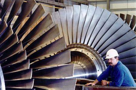
The impulse turbine contains several
"pinwheels" which are actually called turbine rotors, pictured to the
right. The rotors can rotate on a shaft, but cannot slide for and aft. "In
front" of these rotors are nozzles, drilled into the stationary part of
the turbine. Because steam does not like to be confined, each nozzle ejects
steam onto one blade of the rotor, much like we imagined with the
"pinwheel". Because the shape of the blades is at an angle, the jet
of steam must change direction. This change in direction results in a force,
rotating the rotor which rotates the shaft.
One set of turbine rotor and stationary
nozzles is called a stage. Much like the triple expansion piston type engine,
mentioned above, the steam travels through many stages. In the case of steam
turbines, the steam proceeds through one stage, then collects and proceeds to
the second stage and so on. Each time, the steam proceeds to a larger diameter
rotor turbine, until the most of it's energy has been exerted on the rotors of
the turbine. The energy depleted steam is drawn, by vacuum, to thecondenser where it is
cooled to form feed water, ready to feed the boiler once again.
As with any machine, improvements and specific
designs have evolved to improve the overall efficiency of the machine. One
turbine design is the impulse design as describe above. Another is the reaction
type turbine, both types are illustrated below. A third is more of a hybrid
design, combining, actually compounding, features from the impulse and reaction
type steam turbines.
The impulse design (above left) relies on
stationary ring of steam nozzles to direct flow onto the blades of a rotor. In
the reaction type (above right), the flow of steam must pass through the rotor.
The rotor is made up of blades, just like the impulse type, but in this case
the blades  are
curved to provide a slight nozzle shape.
are
curved to provide a slight nozzle shape.
The blades on the impulse type change the
direction of the steam, whilst in the reaction, the blades become the nozzles.
The illustration above show the differences between the two types. The images
to the right, courtesy of Rick Boggs' Merchant Marine and Maritime Pages,
illustrates a reaction type steam turbine.
Steam turbines rotate at very high speeds but
in order to get the most efficiency from the propeller, the propeller must turn
slow. Therefore a marine gear must be used. Marine gears are very common place,
they are used to transform power from an engine to the actual machine doing the
work, in this case the propeller.
 In the picture to the left, the gear is situated behind
the turbine. This is a 20,000hp steam turbine package. You can notice the condenser just below the
turbine assembly.
In the picture to the left, the gear is situated behind
the turbine. This is a 20,000hp steam turbine package. You can notice the condenser just below the
turbine assembly.
Want
more steam ?
Then check the pages below.
Spirax Sarco
has a great deal of information on steam systems and procedures
So who is the "father" of the steam
engine? James Watt, read about him
here.
Visit an informative page on the skinner engine, a reciprocating steam engine.
An interesting site on steam - Steam Esteem from Lars Josefsson
God
bless us all.....:)


